Shenzhen Reunion Electronics Co.,Ltd.
News

How Can a B Series Metal Push-pull Connector Improve Connection Reliability in Demanding Applications

2026-10-14 0 Leave me a message

Reunion develops connector solutions for applications that require dependable electrical connections, convenient operation, and compact integration. The B Series Metal Push-pull Connector is a circular connector designed around a push-pull self-locking mechanism, helping equipment manufacturers establish secure connections while simplifying routine mating and disconnection in industrial, instrumentation, medical, and other electronic applications.

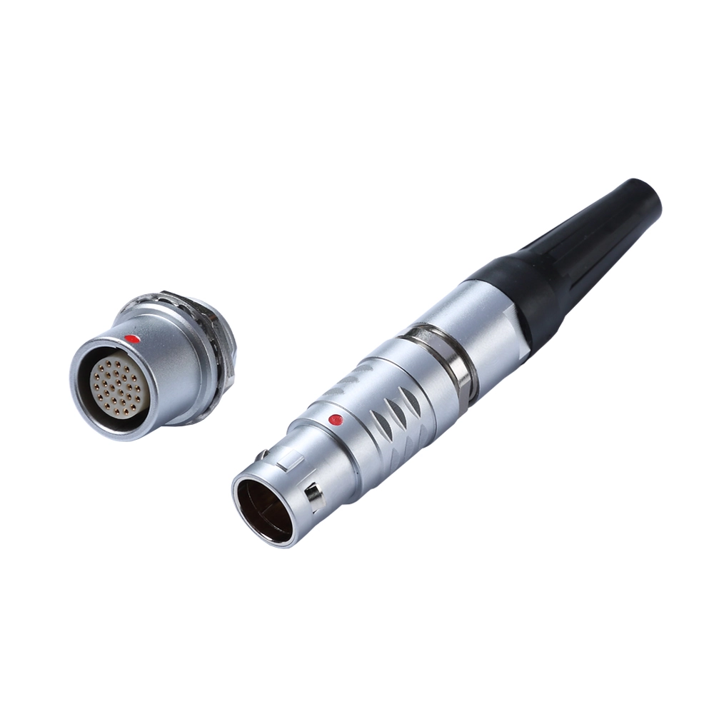
A B Series Metal Push-pull Connector combines a metal circular housing with a push-pull locking mechanism to support fast, secure electrical connections. Depending on the selected configuration, this connector family can accommodate multiple contact arrangements, different mounting styles, and solder, crimp, or PCB termination options. These characteristics make it worth considering for equipment that requires repeated connection, space-efficient installation, and reliable signal or power transmission. This article explains how the connector works, its main design advantages, application scenarios, selection criteria, and quality considerations. It also outlines the technical information buyers should confirm with Reunion before specifying a connector for a new design or replacement project.

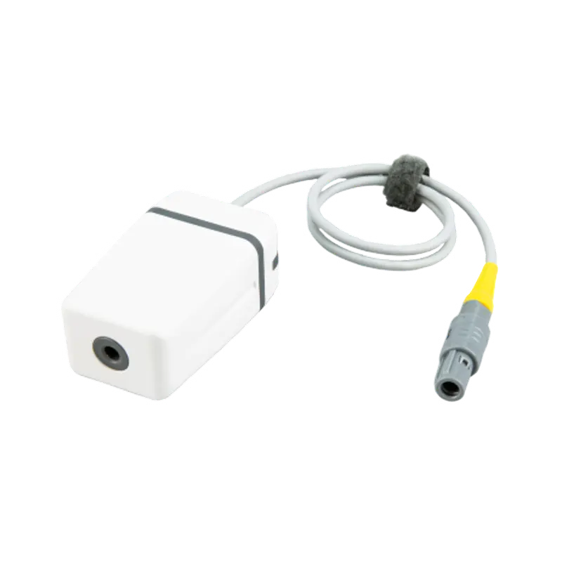
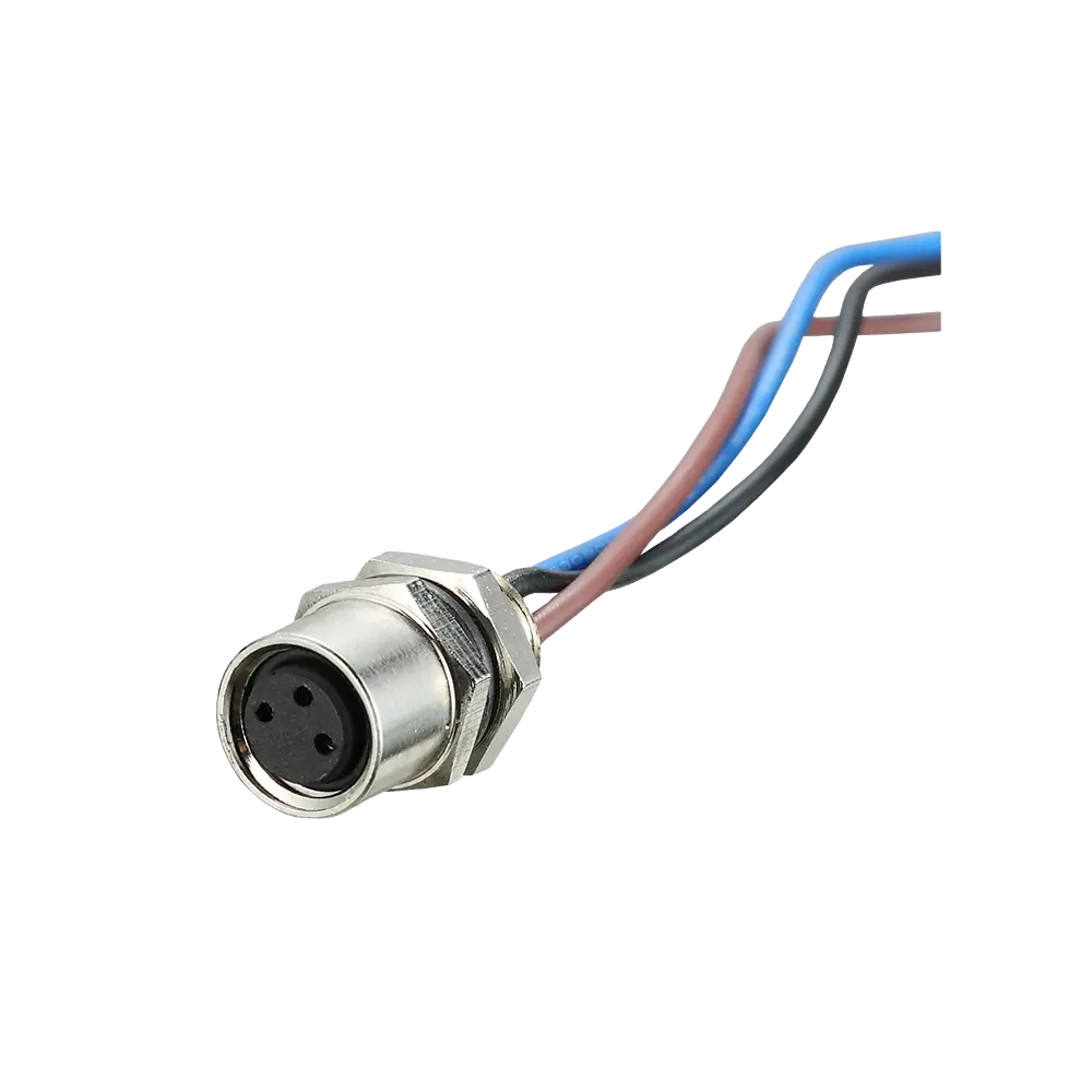
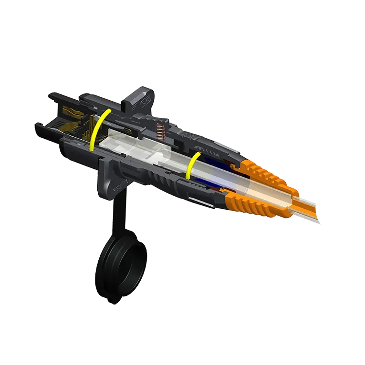
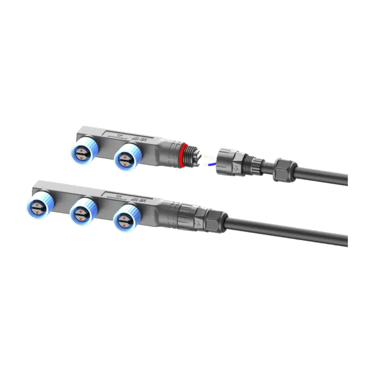
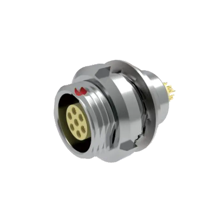
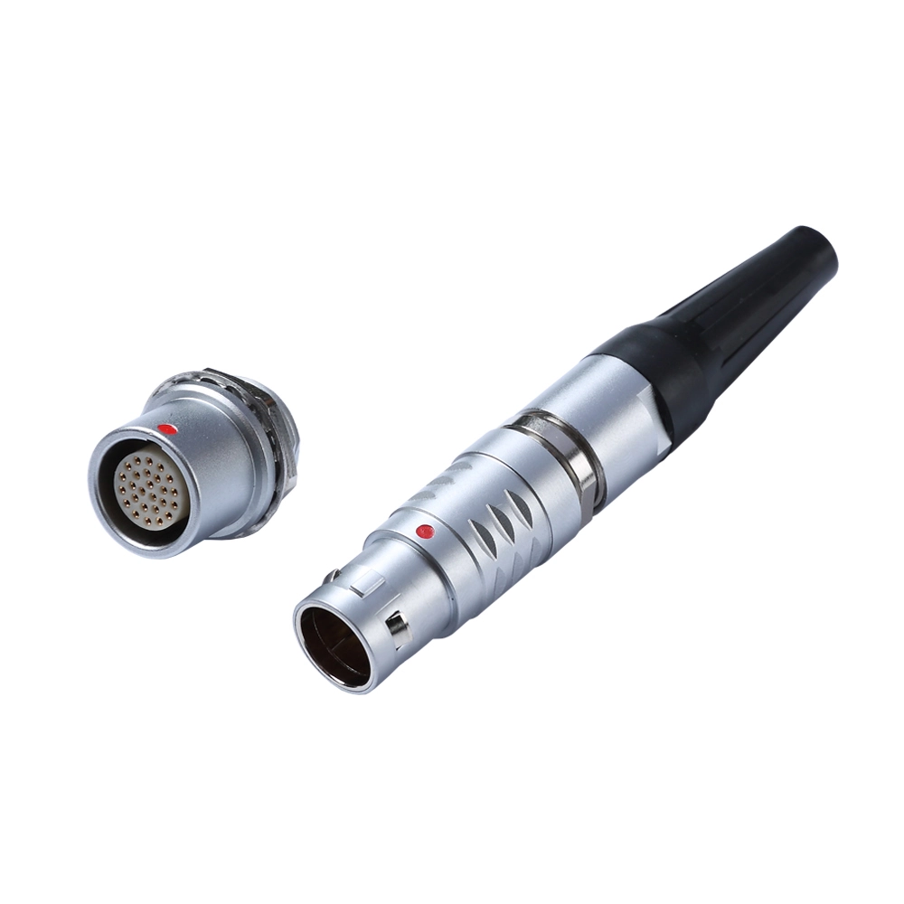
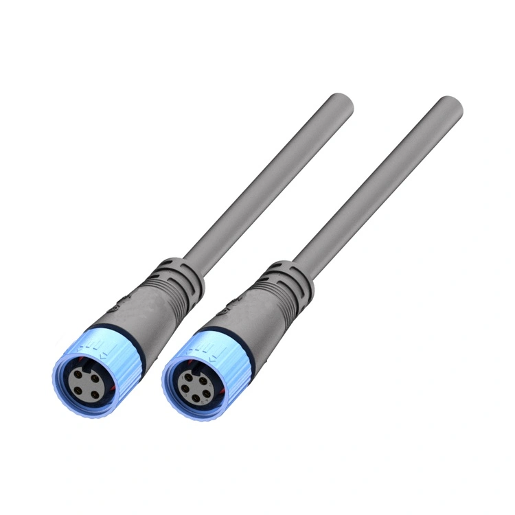
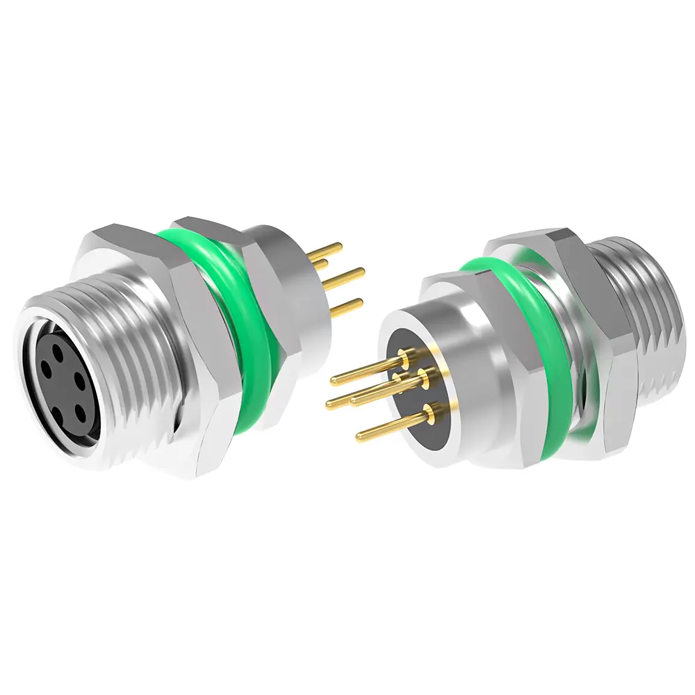
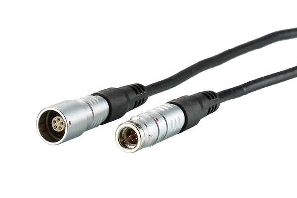
B Series Metal Push-pull Connector

Table of Contents

  1. What Is a B Series Metal Push-pull Connector?
  2. How Does the Push-pull Locking Mechanism Work?
  3. What Are the Main Design Features?
  4. Where Are These Connectors Commonly Used?
  5. How Do You Choose the Right Connector?
  6. Comparison of Connector Selection Factors
  7. Installation and Maintenance Best Practices
  8. What Quality Factors Should Buyers Evaluate?
  9. Frequently Asked Questions
  10. Conclusion

1. What Is a B Series Metal Push-pull Connector?

A B Series Metal Push-pull Connector is a circular electrical connector that uses a push-pull self-latching mechanism to connect and disconnect mating components. Unlike conventional threaded connectors, which typically require rotational tightening, a push-pull design allows users to establish a connection by inserting the plug into its compatible receptacle. The locking mechanism engages when the connector is correctly mated and releases through the designated pull action.

The metal housing provides a robust mechanical interface and may contribute to electromagnetic compatibility when the connector's shielding structure is correctly integrated into the equipment. Depending on the configuration, the connector can support electrical signal transmission, power delivery, or a combination of circuit requirements.

Reunion's B Series product information covers multiple connector sizes and configurations. Available options may include straight or angled constructions, different contact arrangements, and alternative termination methods. Buyers should consult the applicable product drawing and specification to verify the exact features of a selected model.

For detailed product information, visit the Reunion B Series Metal Push-pull Connector page.


2. How Does the Push-pull Locking Mechanism Work?

The push-pull mechanism is designed to make electrical connection operations straightforward without sacrificing the security of the mating interface. Its operation can be understood in three stages.

  • Insertion: The user aligns the plug with the compatible receptacle and pushes the connector into position.
  • Automatic locking: The self-latching mechanism engages when the connector reaches the correct mating position, helping prevent unintended separation during normal use.
  • Disconnection: The user operates the designated release mechanism, typically by pulling the connector body, to separate the mating components.

This operating principle is particularly useful in equipment that requires frequent connection changes, maintenance access, or operation in confined spaces. It can reduce the time spent on repetitive connector handling compared with connection systems that require multiple tightening steps.

However, the locking mechanism should not be treated as a substitute for correct installation. Cable strain, connector misalignment, incompatible mating parts, and improper handling can still compromise connection performance. Users should follow the manufacturer's instructions for mating, release, and cable management.


3. What Are the Main Design Features?

Push-pull Self-locking Operation

The self-latching design supports quick mating and intentional release. It is useful when operators need to connect or disconnect electrical circuits regularly without repeatedly turning a coupling nut.

Metal Circular Housing

The metal shell provides a durable connector structure and can support shielding continuity in appropriately designed systems. Effective electromagnetic interference protection depends on the complete connection, including shell contact, cable shielding, grounding, and installation quality.

Multiple Contact Configurations

Different equipment designs require different numbers of electrical circuits. The B Series family includes multiple contact configurations, allowing engineers to assess options according to signal count, power requirements, available space, and wiring architecture. The exact number of contacts and their electrical ratings must be verified for the selected model.

Flexible Termination Options

Depending on the product configuration, termination choices may include:

  • Solder contacts: Suitable for compatible cable assembly processes that use soldered electrical joints.
  • Crimp contacts: Useful for wiring processes based on controlled mechanical crimping.
  • PCB contacts: Designed for compatible printed circuit board integration.

Contact style, conductor size, assembly tooling, and installation space should be evaluated together before the connector is specified.

Keyed Alignment

Keying features help guide the plug into the correct mating orientation. This can reduce the risk of incorrect alignment and improve assembly consistency, especially when equipment contains multiple similar connectors.


4. Where Are These Connectors Commonly Used?

The B Series Metal Push-pull Connector can be considered for equipment that benefits from a compact circular interface and convenient connection handling. Actual suitability depends on the selected model's electrical, mechanical, and environmental ratings.

  • Medical and diagnostic equipment: Compatible monitoring, diagnostic, and electronic instruments that require dependable connections and convenient maintenance access.
  • Industrial automation: Control equipment, sensors, robotic systems, and machinery interfaces that require organized electrical connections.
  • Test and measurement instruments: Equipment that may need frequent connection changes during inspection, calibration, or laboratory testing.
  • Communication and electronic systems: Signal interfaces where connector size, contact configuration, and shielding integration are important design considerations.
  • Professional audio and video equipment: Compatible systems that require repeated mating and secure cable connections.

For medical, safety-critical, or other regulated applications, the connector must meet the requirements of the complete equipment design. A connector's general product description does not independently establish compliance with every application-specific standard.


5. How Do You Choose the Right Connector?

Choosing a connector based only on appearance or shell size can lead to compatibility problems. Engineers and purchasing teams should evaluate the full electrical and mechanical requirements before placing an order.

Determine the Required Contact Count

Identify how many power and signal circuits the equipment needs. Allow for the intended wiring architecture and confirm whether the selected insert supports the required contact arrangement. Do not assume that connectors with similar external dimensions have identical internal layouts.

Confirm Current and Voltage Ratings

Check the rated current and working voltage for the exact connector configuration. These values can vary with contact diameter, contact count, conductor size, temperature, and operating conditions. The maximum rating of one model should never be applied automatically to the entire series.

Select the Correct Termination Method

Choose solder, crimp, or PCB termination according to the equipment design and manufacturing process. Confirm the required tooling, cable specification, PCB layout, and available assembly space.

Check Mechanical Compatibility

Verify the plug and receptacle part numbers, shell dimensions, panel cutout, mounting arrangement, and cable diameter range. For replacement projects, compare the existing connector's drawings and contact arrangement rather than relying on the product name alone.

Evaluate Environmental Requirements

Review operating temperature, humidity, vibration, mechanical shock, corrosion exposure, and ingress protection. Select a protection level appropriate to the intended environment and ensure that the complete assembled connection meets the requirement.


6. Comparison of Connector Selection Factors

The following table summarizes the main factors to consider when evaluating a B Series connector for a new equipment design.

Selection Factor What to Check Why It Matters
Contact count Number and arrangement of electrical contacts Ensures the connector supports the required circuits
Electrical ratings Rated current, working voltage, and contact specifications Helps prevent electrical overstress and unsuitable operating conditions
Termination type Solder, crimp, or PCB configuration Determines wiring method, tooling, and assembly requirements
Connector orientation Straight or angled construction, where available Helps accommodate cable routing and installation space
Locking and alignment Compatible mating parts and keying arrangement Reduces incorrect mating and unintended disconnection risks
Environmental protection IP rating, temperature, humidity, vibration, and corrosion conditions Supports reliable operation in the intended environment
Service requirements Expected mating frequency and maintenance access Helps determine whether the connector suits the operating workflow

This table is a selection checklist, not a substitute for the official product datasheet. Confirm every critical value against the current technical documentation for the exact part number.


7. Installation and Maintenance Best Practices

Correct installation helps preserve connector performance throughout the equipment's service life. Even a well-designed connector can fail prematurely if it is assembled incorrectly or exposed to conditions outside its rated limits.

  1. Inspect mating components: Check the connector housing, contacts, insulator, and locking components for visible damage or contamination.
  2. Verify compatibility: Confirm that the plug and receptacle are approved mating parts with matching contact arrangements and keying.
  3. Prepare the cable correctly: Follow the specified stripping dimensions, conductor requirements, and termination procedures.
  4. Avoid forced insertion: Align the connector correctly and stop if mating resistance suggests a mismatch or obstruction.
  5. Manage cable strain: Provide appropriate support so that cable weight and movement do not impose excessive force on the connector.
  6. Inspect during maintenance: Look for worn contacts, damaged insulation, loose mounting hardware, contamination, or signs of overheating.

Cleaning methods and lubricants, if any are permitted, should follow the manufacturer's instructions. Unapproved chemicals or abrasive tools may damage contact plating, insulation, or sealing components.


8. What Quality Factors Should Buyers Evaluate?

For OEM projects and repeated production orders, connector quality should be assessed through documented requirements rather than general claims alone. A structured evaluation can help purchasing teams compare suppliers and reduce integration risks.

Before approving a connector, consider the following points:

  • Dimensional consistency: Check the shell dimensions, mounting interfaces, and contact positions against the approved drawing.
  • Electrical performance: Request relevant information on contact resistance, insulation resistance, dielectric strength, and rated operating conditions.
  • Mechanical durability: Confirm applicable mating-cycle and locking-performance data.
  • Material and finish: Review shell material, contact material, plating, and insulation specifications.
  • Environmental suitability: Verify applicable temperature, vibration, humidity, corrosion, and ingress protection test results.
  • Traceability and documentation: Request current datasheets, drawings, inspection records, and other documentation relevant to the project.

Reunion's B Series product page provides a starting point for product evaluation. For critical design decisions, buyers should obtain the current model-specific specifications and confirm that the proposed configuration meets their requirements.


9. Frequently Asked Questions

Q1: What is the main advantage of a B Series Metal Push-pull Connector?

Its main advantage is the combination of push-pull self-locking operation and a metal circular connector structure. This design can simplify repeated mating and disconnection while supporting secure connections in compatible equipment.

Q2: Which termination options are available?

Depending on the selected model, options may include solder, crimp, and PCB contacts. Buyers should confirm the available termination style and assembly requirements for the exact part number.

Q3: Can a B Series connector be used in medical equipment?

It may be suitable for compatible medical and diagnostic equipment when its electrical, mechanical, cleaning, and environmental requirements match the application. The complete device manufacturer must verify all relevant regulatory and safety requirements before use.

Q4: Is every B Series Metal Push-pull Connector waterproof?

No. Environmental protection varies by connector design and configuration. Buyers should check the stated IP rating and whether it applies to the mated assembly, unmated connector, or another specified condition. Do not assume that a metal housing alone provides waterproof protection.

Q5: What information should I provide when requesting a quotation from Reunion?

Provide the required contact count, electrical ratings, plug and receptacle types, termination method, cable dimensions, mounting requirements, operating environment, and estimated order quantity. An existing part number, drawing, or sample can also help the supplier assess compatibility.


10. Conclusion

A B Series Metal Push-pull Connector can be a practical choice for equipment requiring convenient connection handling, secure self-latching, and a compact circular electrical interface. The right configuration depends on contact count, current and voltage ratings, termination method, mechanical compatibility, and environmental requirements. By checking the detailed specifications and validating the connector within the intended equipment, engineers and purchasing teams can make more confident sourcing decisions. Explore the B Series Metal Push-pull Connector from Reunion to review the available product information. If you are planning a new design, replacing an existing connector, or sourcing components for volume production, contact us to discuss your technical requirements, confirm compatible configurations, and request product details for your application.

Related News
Leave me a message
X
We use cookies to offer you a better browsing experience, analyze site traffic and personalize content. By using this site, you agree to our use of cookies. Privacy Policy
RejectAccept